| Ultra Miniature Style Metal Film Resistors - FMR Series | | | | |
| | | | | | | | | | | | | | |
| ULTRA MINIATURE METAL FILM RESISTORS - FMR Series | | |  | | |
| | | | | | | | | | | | |
| TYPE | POWER | | FEATURES | | | | |
| MFR-10 | 0.4W | | Resistance Tolerance: ±1%, ±2%, ±5%. | | | | |
| MFR20 | 0.5W | | Excellent long-term stability. | | | | |
| MFR30 | 0.6W | | High power-to-size ratio for significant space saving. | | | |
| MFR-01 | 1W | | Variety of packing: bulk, strip pack, 26mm and 52mm tape and reel, cut and formen. | | | |
| MFR-02 | 1.8W | | | | | | | | | | | | |
| MFR-03 | 3W | | | | | | | | | | | | |
| | | | | | | | | | | | | | |
| INTRODUCTION | | | | | | | | | | | |
| | | | | | | | | | | | | |
| The FMF Series flame-proof type miniature Metal Film Resistors are manufactured by vacuum depos it metal film on high thermal conductivity and specific gravity Rosenthal ceramic or same grade Japaness rods. The both ends of ceramic are coated with precision mixed metals which help to prevent against noise, and to provide low TCR and low Tol precision resistors the can meet MIL and JIS requirement. | | |
| | |
| | |
| Utilizing a 95~98% of AI ceramic cores and combined a special cutting technology inside, this resulting superior resistors give excellent heat dissipation, stable performance and dignificantly up-grade the power rating. | | |
| | |
| This specially designed resistors are widely used by the industries of communication devices, meters, high-class, audio equipments and precision military defending facilities as well. | | |
| | |
| | | | | | | | | | | | | | |
| DIMENSIONS: | | | | | | | | | | | | |
| | | | | | | | | | | | | |
| STYLE | DIMENSION (mm) | POWER RATING | VALUE | 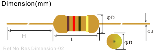 | | |
| L | ΦD | H | Φd | (Watt) | RANGE | | |
| FMR-10 | 3.3±0.4 | 1.8±0.3 | 28±2 | 0.5±0.05 | 0.5W | 10~1MΩ | | |
| FMR-20 | 6.3±0.5 | 2.3±0.3 | 28±2 | 0.6±0.05 | 0.4W | 10~1MΩ | | |
| FMR-30 | 6.3±0.5 | 2.3±0.3 | 28±2 | 0.6±0.05 | 0.6W | 10~1MΩ | | |
| FMR-01 | 6.3±0.5 | 2.±30.3 | 28±2 | 0.6±0.05 | 1W | 10~1MΩ | | |
| FMR-02 | 9.0±0.5 | 3.2±0.5 | 26±2 | 0.6±0.05 | 1.8W | 10~1MΩ | | |
| FMR-03 | 15.5±1.0 | 5.0±0.5 | 32±2 | 0.6±0.05 | 3W | 10~1MΩ | | |
| | | | | | | | | | | | | | |
| ELECTRICAL CHARACTERISTICS: | | | | | | | | | |
| | | | | | | | | | | | | |
| Style | FMR-10 | FMR-20 | FMR-30 | FMR-01 | FMR-02 | FMR-03 | | | | | |
| Power Rating 70oC | 0.5W | 0.4W | 0.6W | 1W | 1.8W | 3W | | | | | |
| Operating Temp. Range | -55oC ~ +155oC | | | | | |
| Max. Working Voltage | 200V | 250V | 250V | 250V | 350V | 500V | | | | | |
| Max. Overload Voltage | 400V | 500V | 500V | 500V | 700V | 1000V | | | | | |
| Dielectric Withstanding Voltage (AC) | 300V | 500V | 500V | 500V | 700V | 1000V | | | | | |
| Max. Intermittence Overload Voltage | 250V | 300V | 300V | 300V | 500V | 1000V | | | | | |
| Value Range ±1%, ±5% | 10Ω ~1KΩ | | | | | |
| Temp. Coefficient (by Type) | ±50ppm, ±100ppm | | | | | |
| * The listed resistance range for standard resistance, below or over this resistance is on request. | | | | | |
| | | | | | | | | | | | | | |
| ENVIRONMENTAL CHARACTERISTICS : | | | | | | | | | |
| | | | | | | | | | | | | |
| PERFORMANCE TEST | TEST METHOD | APPRAISE | | |
| Short Time Overload | JIS-C-5202 5.5 : 2.5 times RCWV for 5 seconds | ±(0.75%+0.05)Ω | | |
| Dielectric Withstanding V. | JIS-C-5202 5.7 : in V-Block for 60 seconds | By Type | | |
| Temperature Coefficient | JIS-C-5202 5.2 : -55oC ~+155oC | By Type | | |
| Insulation Resistance | JIS-C-5202 5.6 : in V-Block | ≧1000 MΩ | | |
| Solderability | JIS-C-5202 6.5 : 230oC for 5±0.5 seconds | 95% min. coverage | | |
| Resistance to Solvent | JIS-C-5202 6.9 : Trichroethance for 1 min. with ultrasonic | no deterioration | | |
| Terminal Strength | Direct load for 10 sec. In the direction of the terminal leads | ≧2.5KG/24.5N | | |
| Pulse Overload | JIS-C-5202 5.8 : 4 time RCWV 10000 cycles(1 sec.on, 25 sec.off) | ±(2%+0.05)Ω | | |
| Load Life in Humidity | JIS-C-5202 7.9 : 40±2oC, 90~95% RH at RCWV for 1000 hrs | ±(3%+0.05)Ω | | |
| (1.5hrs. on, 0.5 hrs. off) | | |
| Load Life | JIS-C-5202 7.10 : 70oC at RCWV for 1000hrs (1.5hrs.on, 0.5hrs.off) | ±(3%+0.05)Ω | | |
| Temperature Cycling | | ±(1%+0.05)Ω | | |
| Soldering Heat | | ±(1%+0.05)Ω | | |
| | | | | | | | | | | | | | |
 | | |
| | |
| | |
| | | | | | | | | | | | | | |
| | |
| | |
| | |
| | |
| | |
| | |
| | |

 Ultra Miniature Style Metal Film Resistors - FMR Series
 ')window.location='/images/stories/food/res-dimension.png')
')window.location='/images/stories/food/res-mfr-04.png')