| Metal Film Resistors - MFR Series | | | | | |
| | | | | | | | | | | | |
| METAL FILM RESISTORS - MFR Series | | | | | | |
| | | | | | | | | |  | |
| Type | Popwer | | FEATURES | | | | | |
| MFR-12: | 1/6W; 1/8W | | MIL-R-1059F. | | | | | |
| MFR-25: | 1/4W | | MFR-12, MFR-25, MFR-50, MFR-100, MFR-200. | | | |
| MFR-50: | 1/2W | | (RN-50, RN-55, RN-60, RN-65, RN-70) | | | | |
| MFR-100: | 1W | | Resistance Tolerance : | ±0.05%, ±0.1%,± 0.25%, ±0.5%,± 1% | | |
| MFR-200: | 2W | | T.C.R. : | 15ppm, 25ppm, 50ppm, 100ppm | | | | | |
| | | | | | | | | | | | |
| INTRODUCTION | | | | | | | | | | | |
| | | | | | | | | | | | |
| The MF series Metal Film Resistors are manufactured using vacuum sputtering system to deposit multiple layers of mixed metals and passivative materials onto a carefully treated fight grade ceramic substrate, the resistors are coated with layers of light-blue lacquer. | |
|
| | | | | | | | | | | | |
| DIMENSIONS: | | | | | | | | | | | |
| | | | | | | | | | | | |
| STYLE | DIMENSION (mm) | POWER RATING | VALUE | | 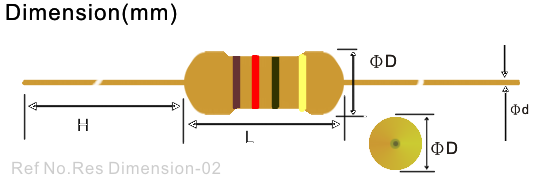 | |
| L | ΦD | H | Φd | (Watt) | RANGE | | |
| MFR-12 | 3.2±0.2 | 1.8±0.3 | 28±2 | 0.43±0.02 | 1/6W 1/8W | 1~10MΩ | | |
| MFR-25 | 6.0±0.2 | 2.3±0.3 | 28±2 | 0.5±0.02 | 1/4W | 1~10MΩ | | |
| MFR-50 | 9±0.5 | 3.2±0.3 | 26±2 | 0.6±0.02 | 1/2W | 1~10MΩ | | |
| MFR-100 | 11.0±0.5 | 4.5±0.5 | 35±2 | 0.7±0.02 | 1W | 1~10MΩ | | |
| MFR-200 | 15.0±0.5 | 5.0±0.5 | 32±2 | 0.8±0.02 | 2W | 1~10MΩ | | |
| MFR-300 | 17.0±0.5 | 6.0±0.5 | 32±2 | 0.8±0.02 | 3W | 1~10MΩ | | |
| | | | | | | | | | | | |
| ELECTRICAL CHARACTERISTICS: | | | | | | | | | |
| | | | | | | | | | | | |
| Style | MF-12 | MF-25 | MF-50 | MF-100 | MF-200 | | | | | |
| Power Rating 70oC | 1/6; 1/8W | 1/4W | 1/2W | 1W | 2W | | | | | |
| Operating Temp. Range | -55oC ~ +155oC | | | | | |
| Max. Working Voltage | 200V | 250V | 350V | 500V | 500V | | | | | |
| Max. Overload Voltage | 400V | 600V | 700V | 1000V | 1000V | | | | | |
| Dielectric Withstanding Voltage (AC) | 300V | 500V | 700V | 1000V | 1000V | | | | | |
| Max. Intermittence Overload Voltage | 400V | 600V | 700V | 1000V | 1000V | | | | | |
| Value Range: ±0.25%, ±0.5%, ±1% | 10Ω ~1MΩ | | | | | |
| Value Range: ±0.05%, ±0.1% | 100Ω ~100KΩ | | | | | |
| Temp. Coefficient (by Type) | ±15ppm, ±25ppm , ±50ppm, ±100ppm | | | | | |
| | | | | | | | | | | | |
| ENVIRONMENTAL CHARACTERISTICS : | | | | |
| | | | | | | | | | | | |
| PERFORMANCE TEST | TEST METHOD | APPRAISE | |
| Short Time Overload | JIS-C-5202 5.5 : 2.5 times RCWV for 5 seconds | ±(0.75%+0.05)Ω | |
| Dielectric Withstanding V. | JIS-C-5202 5.7 : in V-Block for 60 seconds | By Type | |
| Temperature Coefficient | JIS-C-5202 5.2 : -55oC ~+155oC | By Type | |
| Insulation Resistance | JIS-C-5202 5.6 : in V-Block | ≧1000 MΩ | |
| Solderability | JIS-C-5202 6.5 : 230oC for 5±0.5 seconds | 95% min. coverage | |
| Resistance to Solvent | JIS-C-5202 6.9 : Trichroethance for 1 min. with ultrasonic | no deterioration | |
| Terminal Strength | Direct load for 10 sec. In the direction of the terminal leads | ≧2.5KG/24.5N | |
| Pulse Overload | JIS-C-5202 5.8 : 4 time RCWV 10000 cycles(1 sec.on, 25 sec.off) | ±(2%+0.05)Ω | |
| Load Life in Humidity | JIS-C-5202 7.9 : 40±2oC, 90~95% RH at RCWV for 1000 hrs | ±(3%+0.05)Ω | |
| (1.5hrs. on, 0.5 hrs. off) | |
| Load Life | JIS-C-5202 7.10 : 70oC at RCWV for 1000hrs (1.5hrs.on, 0.5hrs.off) | ±(3%+0.05)Ω | |
| Temperature Cycling | | ±(1%+0.05)Ω | |
| Soldering Heat | | ±(1%+0.05)Ω | |
| | | | | | | | | | | | |
 | |
|
|
| | | | | | | | | | | | |
|

 Metal Film Resistors - MFR Series
')window.location='/images/stories/food/res-dimension.png')
')window.location='/images/stories/food/res-mfr-04.png')